Tubular Screw Conveyor Specification: Diameter, Pitch and Fill in One Calculation
Screw conveyor capacity is cross-section times linear speed times bulk density — but the fill factor and the incline angle decide which of those numbers you actually get.
Capacity is a product of diameter, pitch, speed and bulk density, corrected by a fill factor.
Fill factor is a material property: free-flowing products tolerate high fill, abrasive or sticky ones do not.
Every few degrees of incline costs throughput, because material falls back along the screw.
Speed must be matched to the product — faster is not better for fragile or abrasive materials.
Measure bulk density on your own material; a figure borrowed from a similar project is not a substitute.
Technical Overview
The capacity equation, and what it hides
For a horizontal screw conveyor, throughput is the cross-sectional area of the material bed multiplied by the linear speed of the material, multiplied by its bulk density. Linear speed is simply pitch times rotational speed — the distance material is pushed forward in one revolution. Written out, that is the standard form most engineers quote: capacity equals a constant times diameter squared, times pitch, times rpm, times bulk density, times fill factor. The equation is not difficult. The difficulty is that three of its inputs — pitch relationship, fill factor and bulk density — are material-dependent, and getting them wrong is easy.
Fill factor is where most mistakes are made
The fill factor expresses what fraction of the trough cross-section is actually occupied by material in normal operation. It is not a fixed constant. Free-flowing, non-abrasive products can be conveyed at relatively high fill, while abrasive, sticky or heavy products have to be run much lower to limit friction, wear and torque. Using a generous fill factor for a cohesive mineral powder produces a specification that looks fine on paper and trips its motor on day one. Where a real figure is not available, conservative values and a test with the actual product are the only safe route.
Diameter, pitch and speed are one decision
Diameter sets how much material can pass; pitch sets how fast it is advanced; speed sets the intensity of the action. They have to be chosen together. Standard pitch — roughly equal to the diameter — suits most horizontal duties. Shorter pitch is used on steeper inclines or where the screw acts as a feeder, because it reduces backflow. Longer pitch moves more volume per revolution but is less common. Increasing speed to gain capacity has a cost: more degradation of fragile product, more wear on flights and trough, and higher power demand per tonne.
Incline is the silent capacity thief
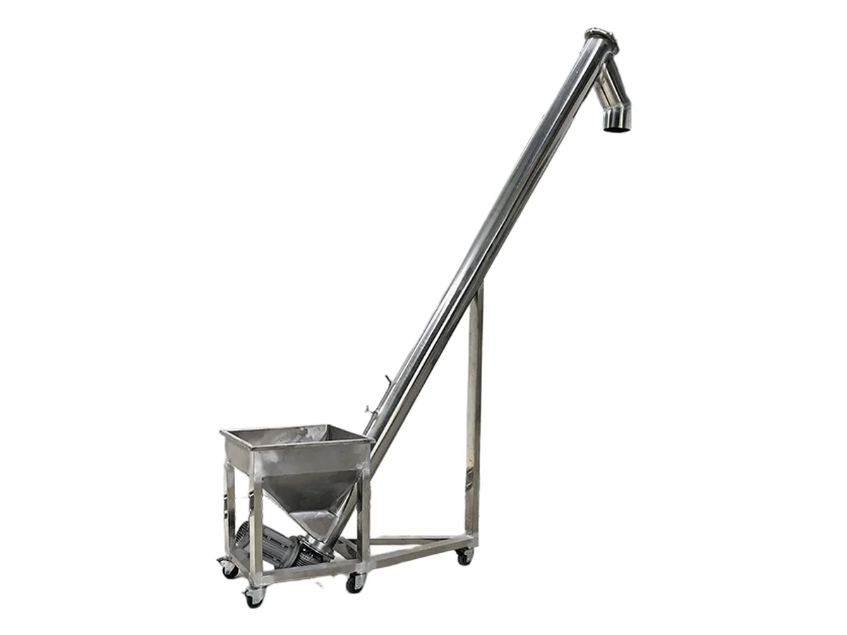
Horizontal conveying is the most efficient case. As the upward angle increases, more material falls back along the screw instead of advancing, and the effective capacity falls — mildly at shallow angles, sharply beyond roughly twenty degrees. The usual correction is a bigger screw, a shorter pitch or a higher speed, but each of those has a penalty elsewhere. Beyond about thirty degrees you are generally better served by a different machine rather than a heavily de-rated screw. Where layout forces an incline, place it near the end of the run where velocity is highest, and keep the angle shallow.
Flight type follows the material
Standard helicoid flights on a centre pipe handle free-flowing to mildly sluggish products. Heavier or more abrasive duty calls for thicker flights, hard-facing or replaceable wear sections. Pasty, fibrous or sticky products suit ribbon or paddle constructions that do not pack around a shaft. Very sticky or stringy materials are the case for a shaftless spiral, where the absence of a centre pipe removes the surface that material wraps around. Getting this wrong does not usually cause an immediate failure — it causes a slow decline in throughput and a rise in cleaning frequency that nobody connects to the original specification.
Clearance, bearings and length limits
The running clearance between flight and trough has to be small enough to limit back-leakage but large enough to tolerate shaft deflection, thermal expansion and fabrication tolerance. On long machines, intermediate hanger bearings support the shaft — and they are the component most likely to fail in sticky or abrasive service, since product packs into the housing. Practical single-section lengths are therefore limited, and longer routes are built from coupled sections with a drive on each. Where the product is genuinely difficult, the shaftless arrangement removes the hanger bearing problem entirely.
Information for a proper specification
Send the material name, loose and tapped bulk density, particle size distribution, moisture, temperature and abrasiveness. Give the required capacity and whether it is continuous or intermittent. Give the route: horizontal and vertical distances, number and radius of bends, inlet and outlet positions. State what feeds the screw and what it discharges into, plus the sealing and dust requirements, materials of construction, available voltage and enclosure rating, and the site's hazardous-area classification. With those answers CHUYAO can size the flight geometry, drive and sealing to the duty rather than to a catalogue page.
Process Flow
Typical steps covered in this article.
Inlet Feed
Screw Flight Transport
Intermediate Support
Outlet Discharge
Drive & Sealing
Typical Applications
Metering powder from a hopper to a mixer
Dust discharge from filter hoppers
Horizontal or inclined transfer between process stages