Projects
Project Gallery
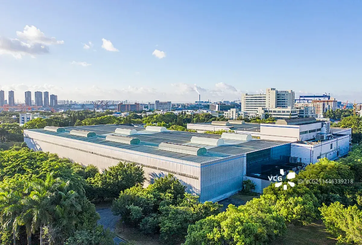
On-site installations, equipment and our manufacturing facility.
Inside our projects and workshop
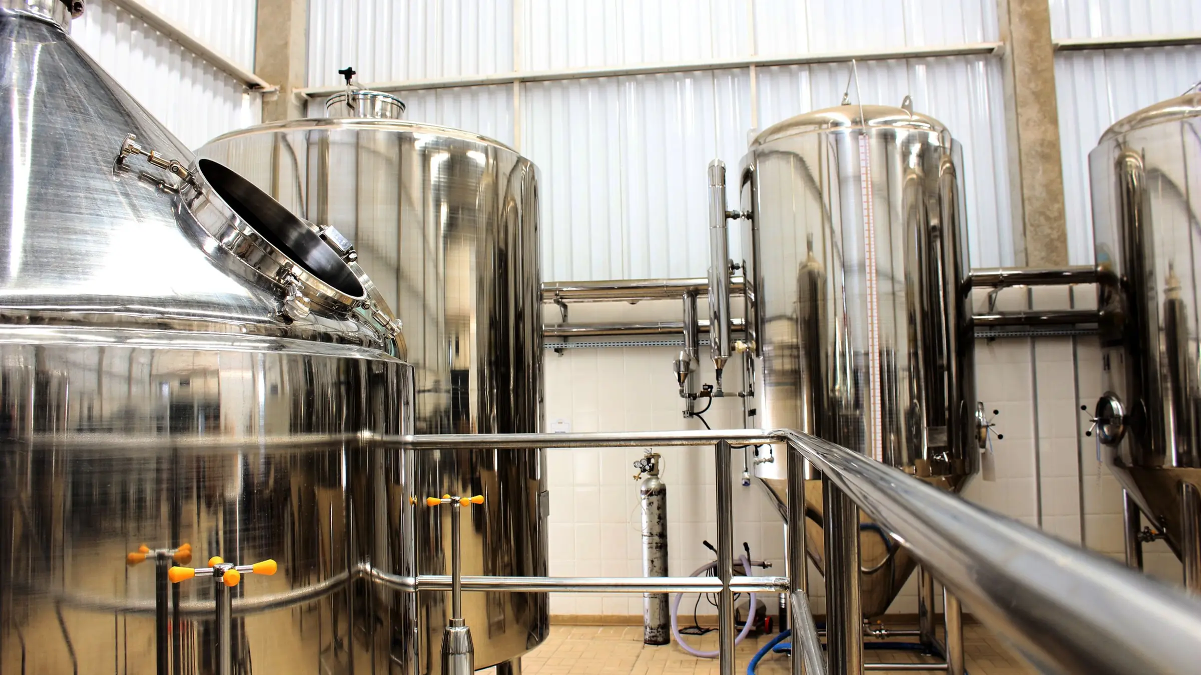
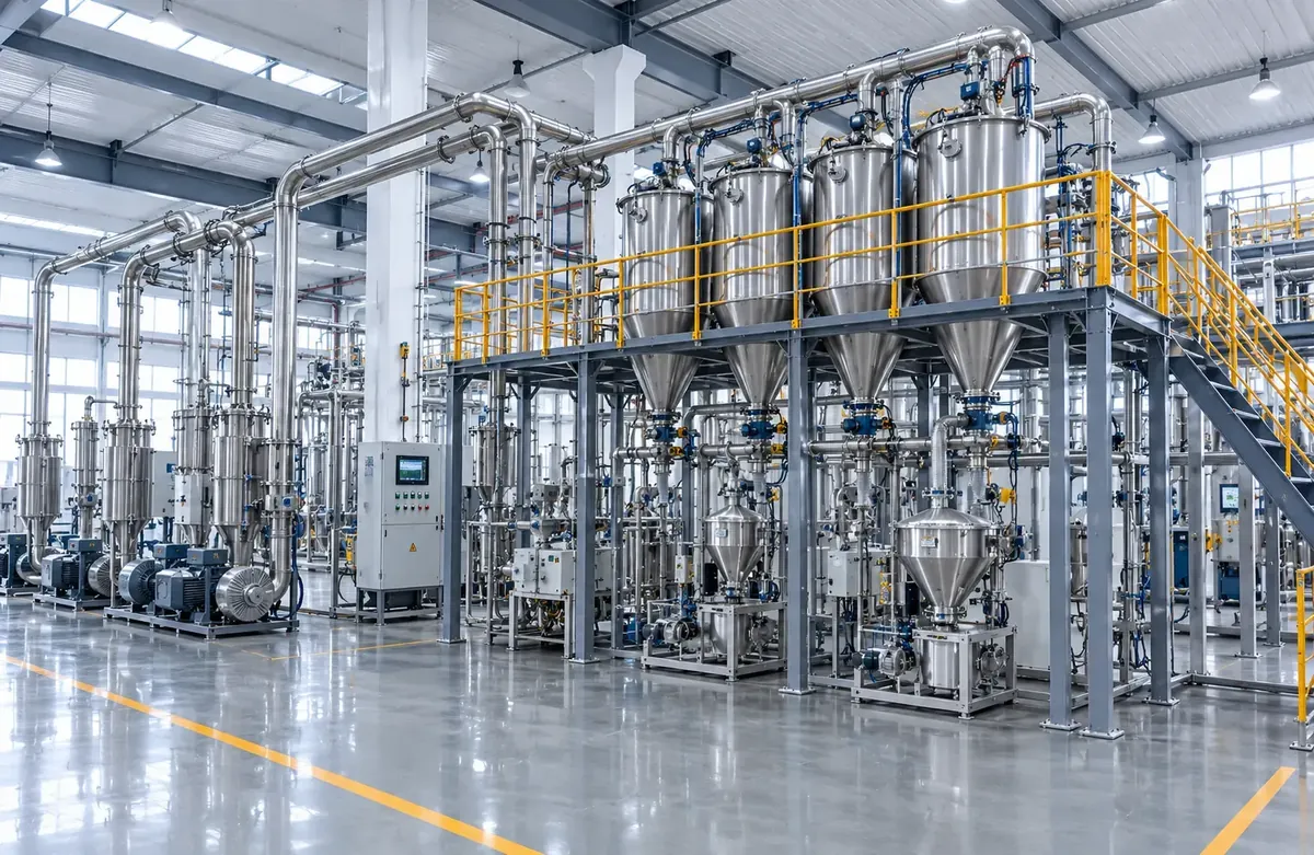
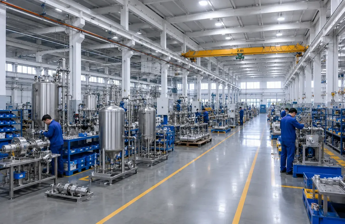
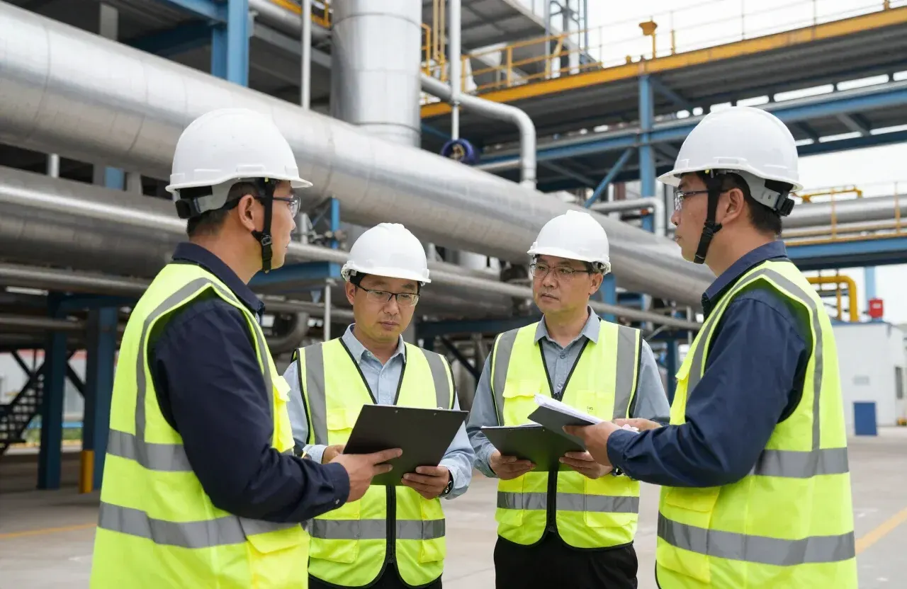
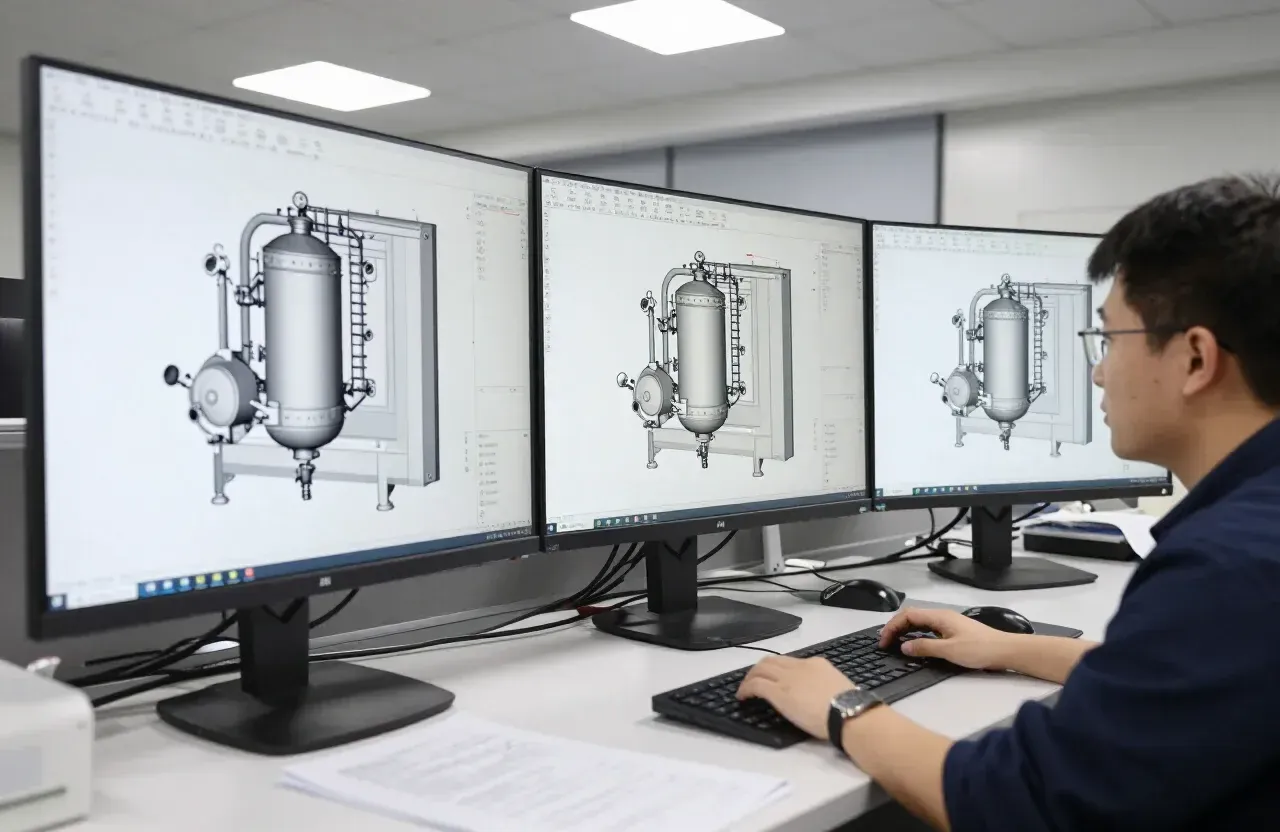
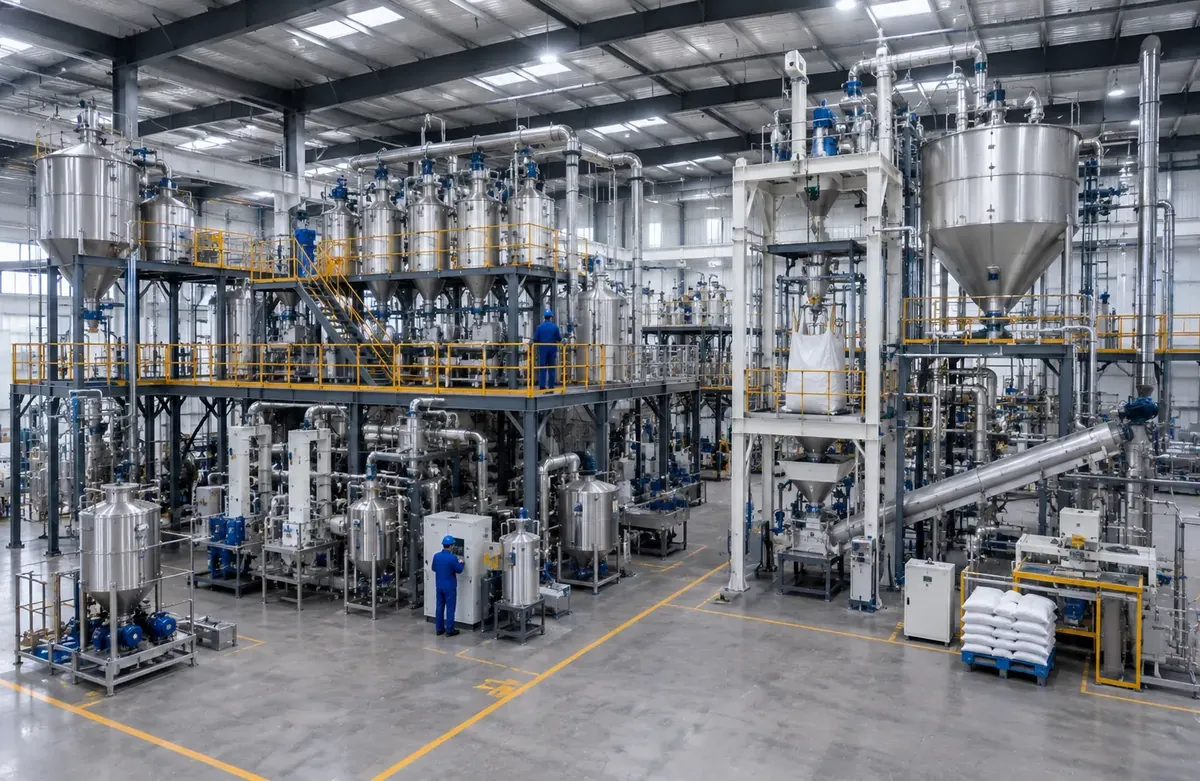
This gallery collects installation and factory photographs from powder handling projects - vacuum conveying lines on site, central feeding installations, assembly work in our workshop and complete process packages. The photographs are taken at handover, so they show the equipment as it was installed rather than as a render.
Every project starts from three questions: what the material is, what capacity is needed, and what the existing plant looks like. From there we select intake, conveying, dosing and packing equipment, issue layout drawings and utility requirements, and commission the line on site. The images here are grouped by what they show, not by order of delivery.
What photographs show that drawings do not
Installed photographs are useful for a second reason: they show the constraints a drawing cannot. How much headroom was available above a receiver. How piping was routed around existing steelwork. Where filters and access covers were placed so they can be reached for maintenance. How the packing area was kept clear of hoses and empty bags.
- Vacuum conveying lines installed above process areas and walkways.
- Assembly and testing of receivers, hoppers and support frames.
- Central feeding systems serving several machines from one intake.
- Bag dump, FIBC unloading and packing areas.
- Complete powder processing plants photographed at handover.
If a photograph looks close to the duty you have in mind, send us the material and the capacity and we can share the equipment list used on that project, along with the drawings that were issued for it.
Reusing a layout on a new project
An installed line is a useful starting point when a second plant handles a similar powder. The intake arrangement, the number of conveying points, the receiver positions and the packing station can often be carried over, while pipe diameter, vacuum pump size and filter area are recalculated for the new capacity and route length. That normally shortens both design time and the discussion about how the equipment will fit into the building.
It is worth saying which parts of an installation are fixed and which are adjustable. Floor cut-outs, ceiling height and the position of existing steelwork usually decide the layout; receiver size, piping routes and control panels are the parts we can move to suit them.