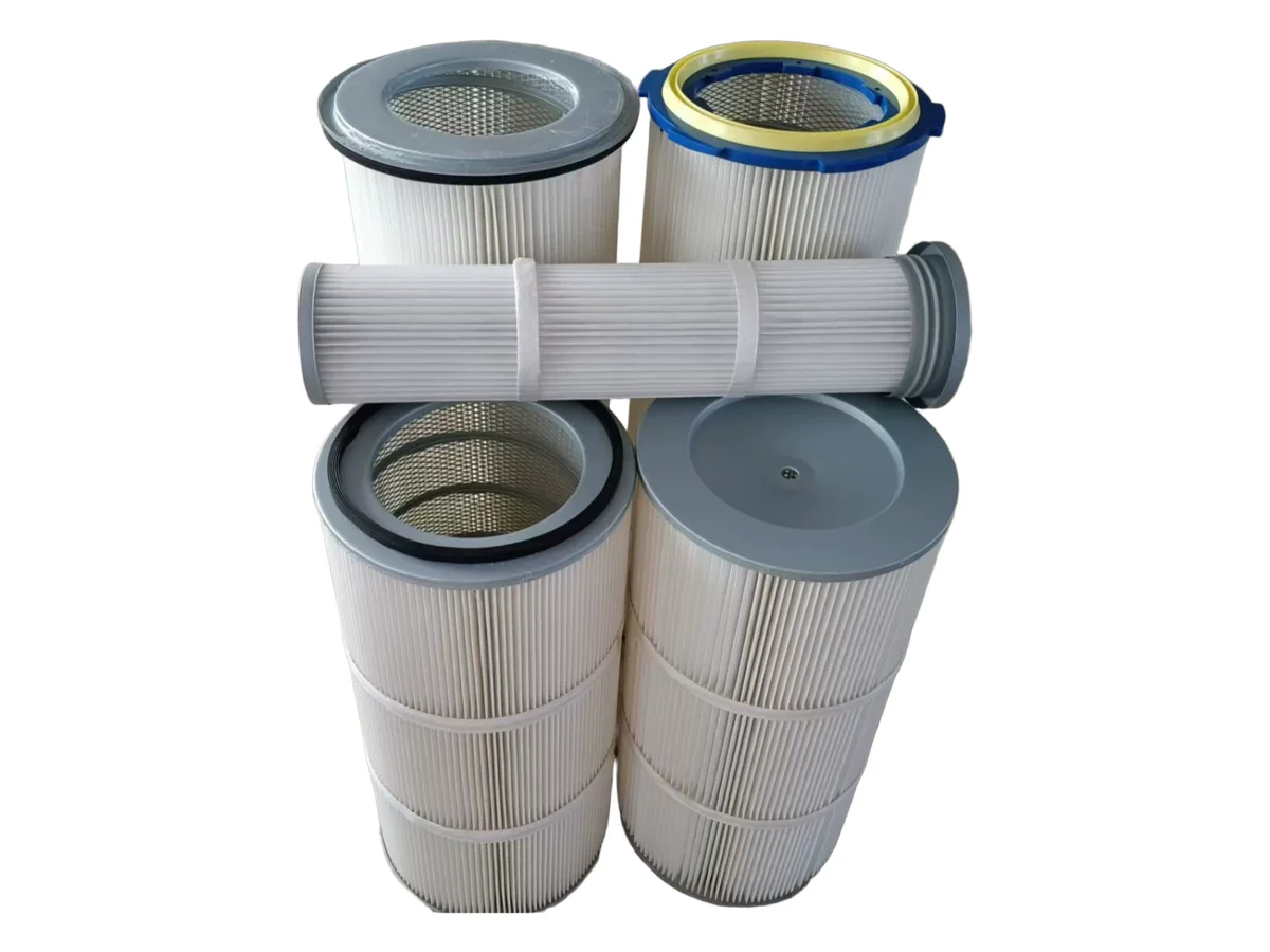
Combustible dusts need earthing, anti-static filter media and a documented risk assessment.
Technical Overview
What is a vacuum conveyor?
A vacuum conveyor (also called a vacuum conveying system) transfers powders, granules and bulk solids through a sealed pipeline using negative pressure. Because the product travels inside closed tubing, dust exposure is minimized, material integrity is protected, and operators avoid open mechanical conveyors. For food, pharma, chemical and battery plants, this enclosed transfer is often preferred over belt or screw conveyors when hygiene, containment or layout flexibility matters.
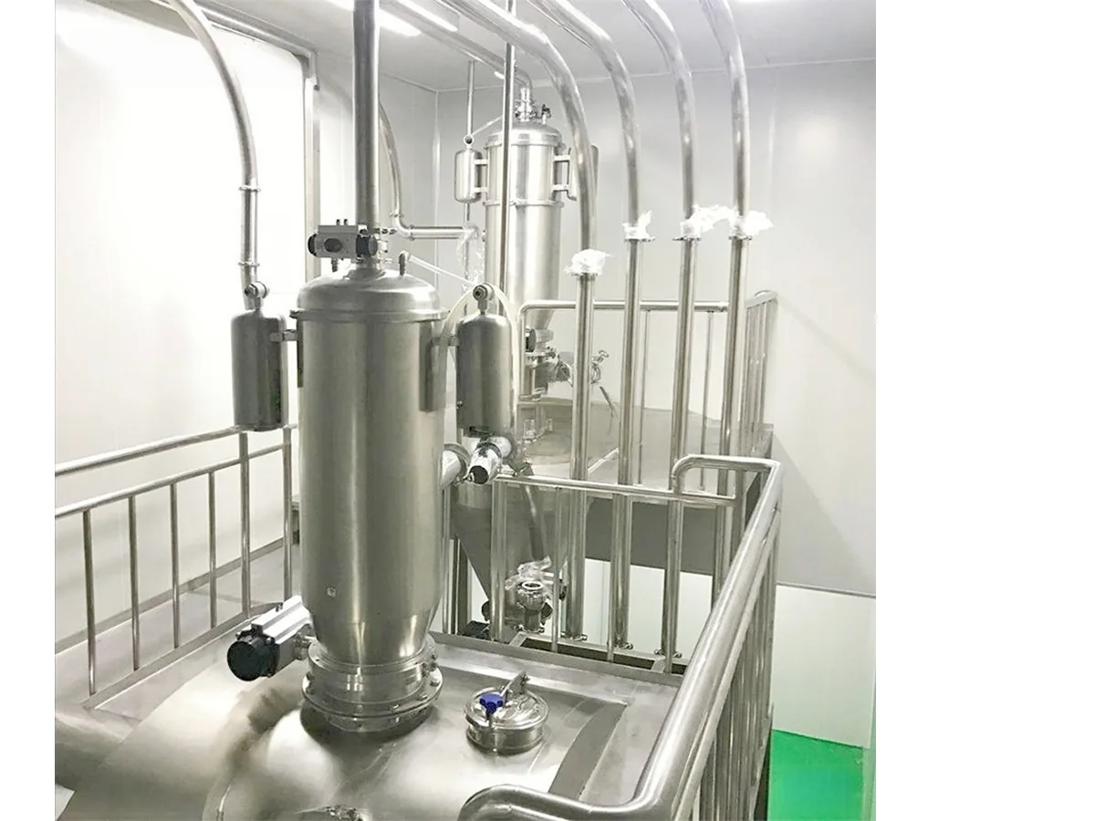
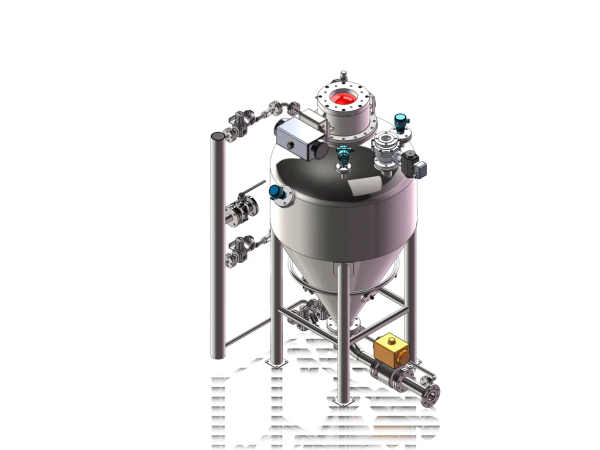
Vacuum conveyor receiver with integrated filtration for dust-free powder transfer
How the system works
At the pickup point — bag dump station, big bag unloader, silo outlet or process hopper — air and product are drawn into the line. The mixture travels through the pipeline to a receiving hopper, where material settles and air is separated. Filters clean the conveying air before it reaches the vacuum pump or blower. A rotary valve, butterfly valve or discharge gate then feeds the next process step (mixer, screener, reactor, packing machine or another conveyor). Cycle times can be continuous or intermittent batch mode depending on capacity and downstream demand.
Enclosed pipeline routes powder from intake to process equipment without open transfer
Material intake: bag dump and big bag unloading
Most vacuum systems start at a controlled intake point. Bag dump stations provide an ergonomic sack-tipping surface with local dust extraction, so operators can empty 25 kg bags without creating a dust cloud. Big bag (FIBC) unloaders add hoist or forklift loading, dust-tight spout clamps and massage paddles for cohesive powders. From either station, a pickup adapter connects directly to the vacuum line so product never spills onto the floor.
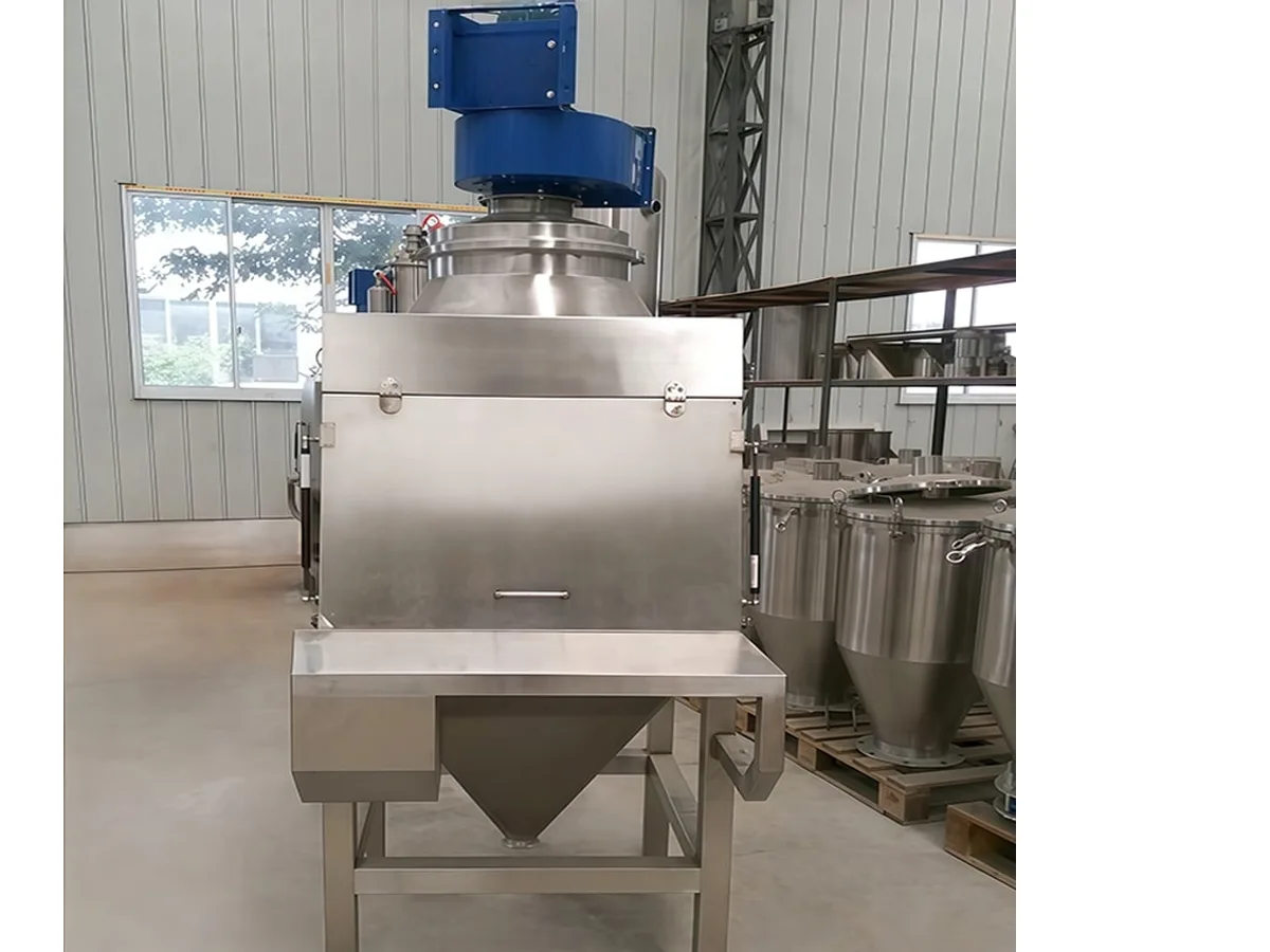
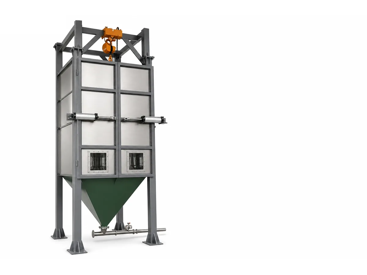
Bag dump station — common pickup point for vacuum conveying systemsBig bag unloader for bulk FIBC discharge into the conveying line
Main system components
A complete vacuum conveying line typically includes a pickup adapter or suction wand, conveying pipe and bends, a receiving hopper with level control, a filter unit (cartridge or bag), a vacuum pump or regenerative blower, and a discharge device. Optional items include CIP-ready stainless steel construction, in-line weighing, multi-point routing valves and PLC recipe control for multi-ingredient batching. Correct matching of pipe diameter, bend radius and pump capacity is essential for stable conveying without plugging.
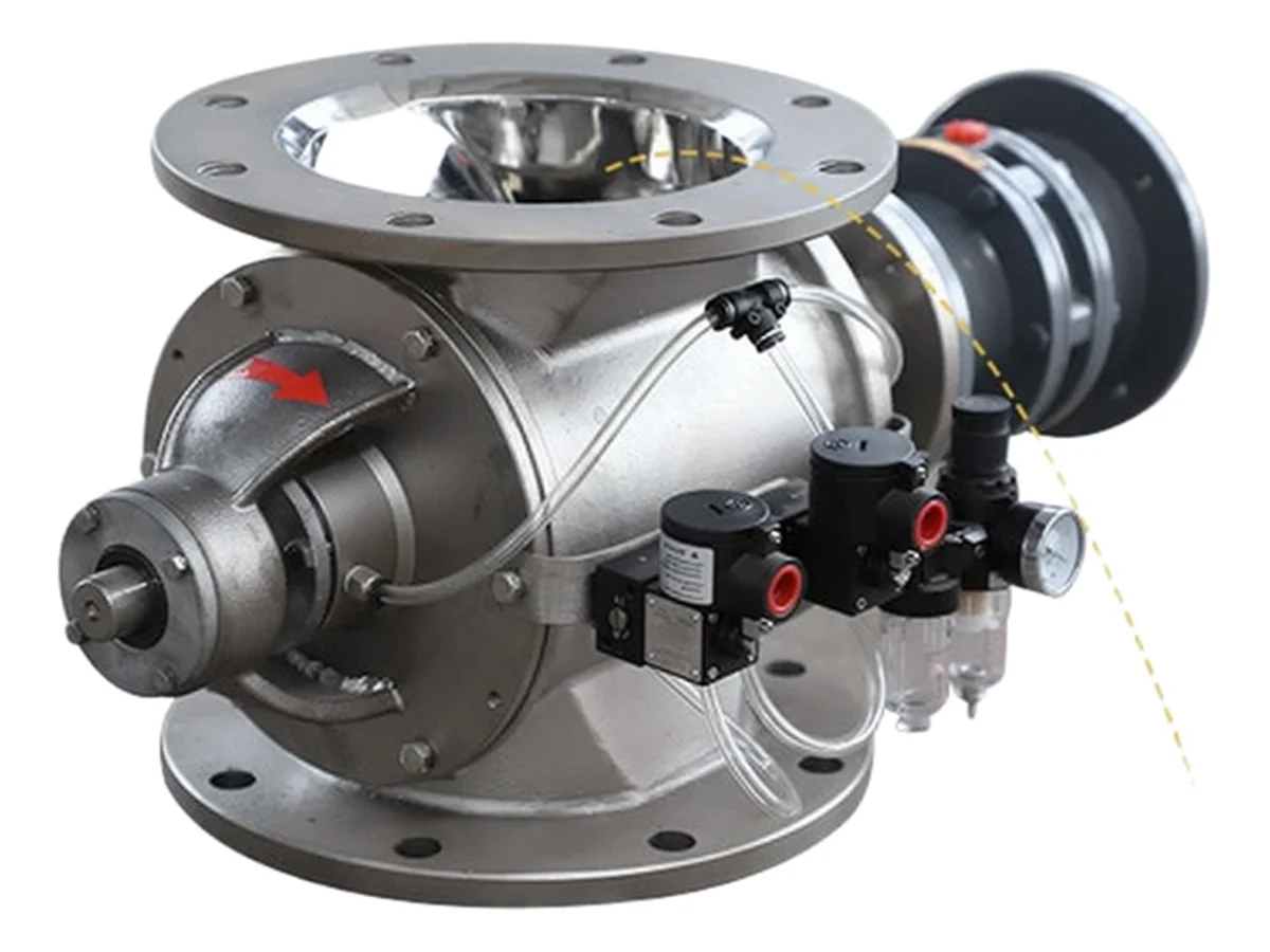
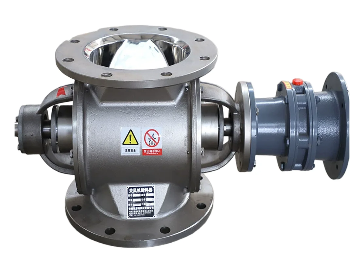
Rotary airlock valve — meters product out while helping maintain vacuum in the receiver
Discharge: intermittent or continuous?
A vacuum receiver does not convey in a steady stream — it fills, and then it must empty itself again before the next cycle can start. How it empties shapes the whole system. Intermittent discharge is the usual choice for feeding mixers, hoppers, vibrating screens and packing machines: powder collects in the receiver, then a flap or butterfly valve opens and drops it in one short burst, and the cycle repeats on a timer or on a level signal. Continuous discharge keeps a rotary airlock working against the vacuum, releasing product steadily rather than in pulses; it suits long routes and steady high rates, but costs more and needs a different control philosophy. Intermittent units are mechanically simpler and give dependable level control, which is why they dominate indoor transfers. Continuous units avoid the surge that can upset a downstream weigher or a loss-in-weight feeder. Our receiver range is split along the same line — model codes ending in L are the continuous-discharge versions.
Continuous discharge relies on a rotary airlock that releases product while holding vacuum
Dilute phase vs dense phase
Most vacuum conveyors operate in dilute phase: high air velocity, lower solids loading, suitable for free-flowing powders over short to medium distances. Dense-phase systems use lower velocity and higher product concentration, reducing wear and degradation for abrasive or fragile materials, often over longer routes with positive-pressure pneumatic conveying. Selection depends on material properties, distance, capacity and degradation limits. In many plants, vacuum dilute-phase covers indoor transfers between equipment, while dense-phase handles longer silo-to-process routes.
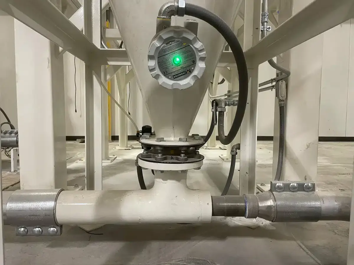
Pneumatic conveying hardware used for dilute- and dense-phase powder transfer
Design factors that matter
Specify particle size, bulk density, moisture, abrasiveness and explosibility (ATEX / dust explosion class). Match pipe diameter and pump capacity to the required throughput and conveying distance. Size filters for continuous or intermittent duty, and choose discharge airlocks that maintain vacuum while feeding downstream equipment. Plant layout — vertical lifts, number of bends, multi-destination routing — strongly affects power consumption and reliability. Early material testing (bulk density, angle of repose, particle size distribution) reduces commissioning risk.
Central feeding layout — one vacuum network supplying multiple machines
Data to collect before sizing a system
When a conveying line underperforms, the cause is nearly always a material or route detail that nobody measured at the outset. Five groups of information decide the design. First the material itself: name, loose and tapped bulk density, particle size distribution, moisture content, stickiness or caking tendency, and abrasiveness. Then the throughput: required capacity in kg/h, and whether demand is steady or intermittent. Then the route — horizontal and vertical distance and, above all, the number of bends, since each bend costs far more pressure than an equivalent length of straight pipe. Then the endpoints: how many pickup points and how many destinations, and what equipment sits at each end. Finally the environment: hygiene class, whether an ATEX or inert-gas regime applies, and ambient temperature and humidity. Bulk density matters more than most people expect, because the same receiver volume holds very different masses of flour and of a dense mineral filler, so a figure borrowed from a similar project is never a substitute for testing your own material.
Sizing starts with measured material data, not with a quote from a similar project
Dust explosion safety
Any powder fine enough to stay airborne can form an explosive atmosphere, and the inside of a receiver, filter housing or duct is exactly where such a cloud tends to collect. Vacuum conveying is inherently safer than open transfer because the product stays enclosed and stray ignition sources are easier to exclude — but the enclosure then becomes the place where the risk concentrates. The practical measures are well established: earth-bond and continuity-test every conductive component, including flexible hose, which should carry a wire helix; fit anti-static filter media; avoid generating unnecessary fines; provide explosion venting or suppression where the risk assessment calls for it; and consider inert-gas blanketing with dew-point monitoring for solvent-wet or very fine products. Which protection method applies, and how zones are classified, is a decision for a documented risk assessment of your own material and plant rather than for a catalogue page.
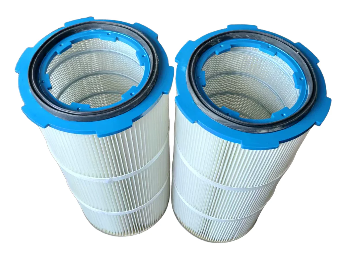
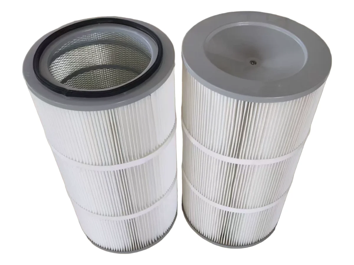
Filter media and earthing are the first line of defence against dust explosion risk
Common operating problems and their causes
Four problems account for most service calls. Capacity that drifts down over weeks is almost always a filter issue: the elements are loading faster than the reverse-pulse can clear them, or the pulse air supply has fallen below its working pressure or picked up moisture. A line that plugs has usually been given too much air at the pickup, or is handling material wetter or more cohesive than the design assumed — a partly closed discharge valve has much the same effect. Wear and product degradation point to conveying velocity being too high for the material, which abrasive minerals punish quickly; increasing the pipe diameter over the same route is often the cheapest correction. And a vacuum source running hot or unusually loud usually means fines are passing the filter, so check element integrity and any secondary filtration before assuming the blower itself is at fault.
Most capacity complaints trace back to the filter, not to the conveying principle
Maintenance that keeps capacity stable
Vacuum conveying has few moving parts, and most of its upkeep is inspection rather than repair. The filter element is the wear item that matters most: inspect it on a fixed interval, replace it once a pulse no longer restores airflow, and never substitute a lower grade, because a cheap element that fails puts dust straight into the vacuum source. Discharge valve seals and airlock clearances wear with abrasive products and should be checked against their original clearance. Confirm that the pulse air is dry and oil-free, since moisture in the pulse line is a common cause of caked filters that present themselves as a capacity problem. Receivers built with quick-clamp assemblies open without tools, which makes routine inspection something an operator can genuinely do between shifts. Finally, log conveying time per cycle: a slow upward drift is the earliest warning that the filter is loading, and it arrives long before production stops.
A fixed filter inspection interval is the single most effective maintenance habit
When to choose vacuum conveying
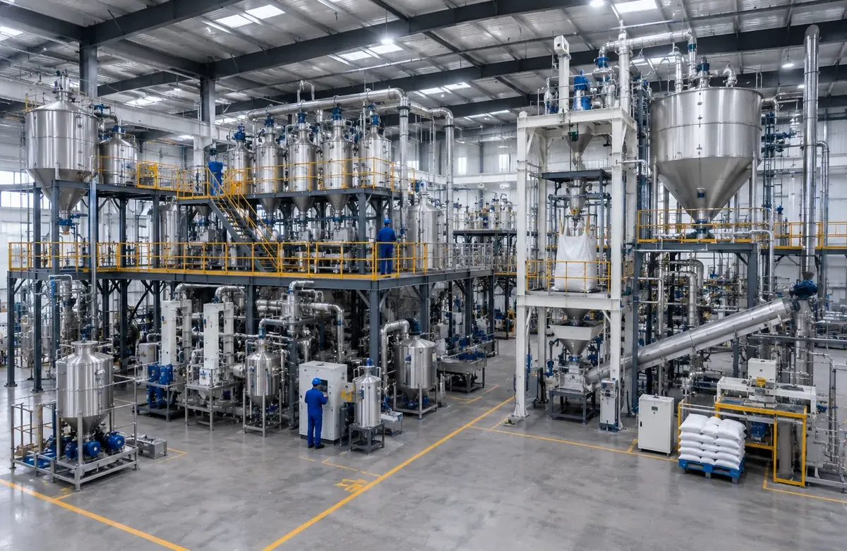
Vacuum conveying is ideal when you need dust-free transfer, flexible routing around existing equipment, hygienic stainless construction, or gentle handling of free-flowing powders into mixers, reactors and packaging lines. For very long distances, highly abrasive products or extremely high capacities, dense-phase pneumatic conveying or mechanical conveyors may be more economical — our engineers can compare options against your material and layout. Many complete powder plants combine bag dump / big bag intake, vacuum transfer, weighing and packaging in one integrated line.
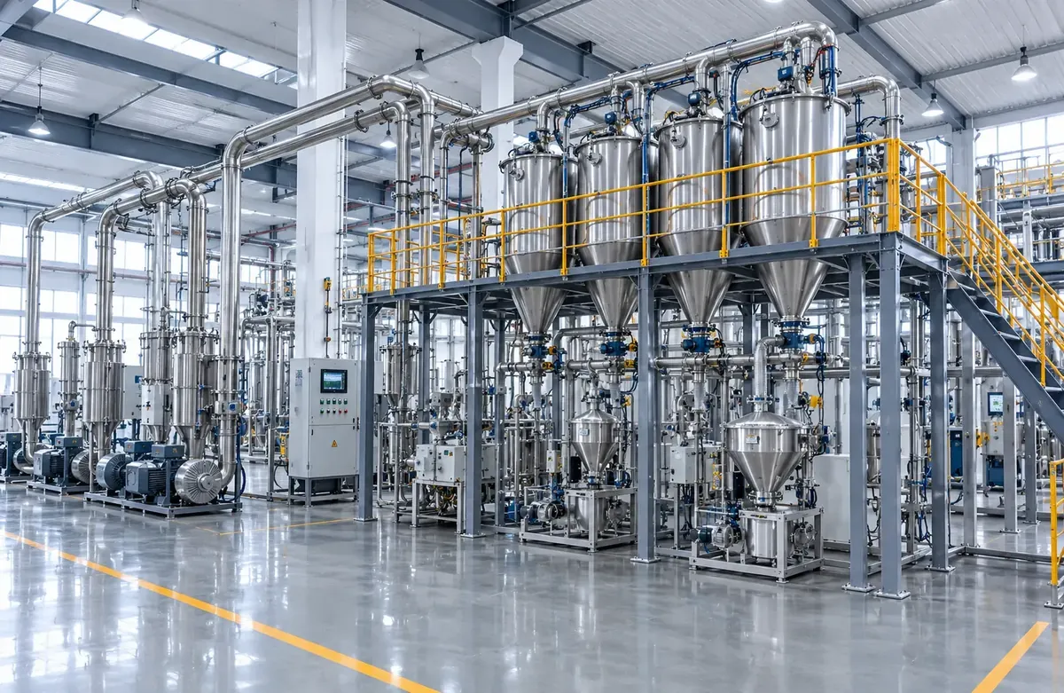
Integrated powder plant: intake, conveying, dosing and packaging in one line
Process Flow
Typical steps covered in this article.
Material Pickup
Pipeline Transfer
Receiving & Separation
Filtration
Vacuum Source
Typical Applications
Food & dairy powder transfer
Pharmaceutical and API handling
Battery cathode / anode powders
Chemical additives and pigments
Central feeding to mixers and packers
Project Gallery
Real installations related to the systems described above.
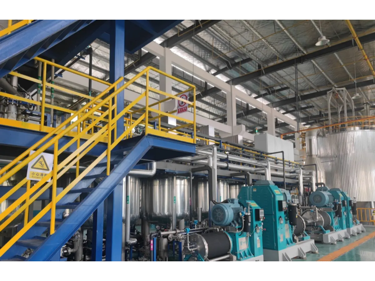
On-site vacuum conveying line feeding multiple process pointsCentral vacuum feeding network in a powder processing plantComplete powder handling line with conveying, dosing and mixing
Equipment
Related Products
Explore equipment commonly used with the processes described in this article.