Rotary Airlock Valve Sizing: Clearance, Speed and Leakage Air
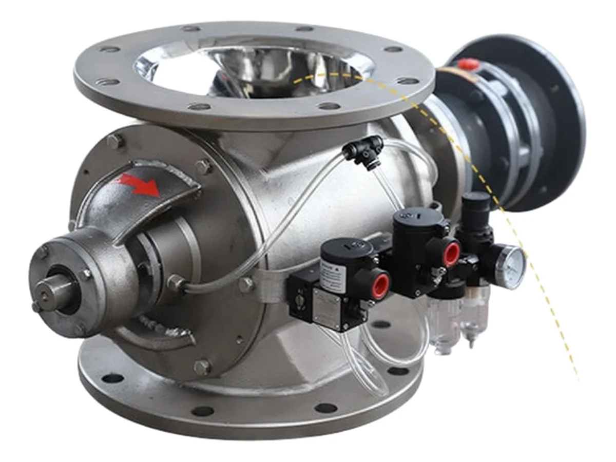
A rotary valve is both a meter and an airlock, and those two jobs pull in opposite directions. Sizing it means deciding where on that tension your process sits.
Tip speed limits protect both product integrity and ATEX ignition safety.
Abrasive products increase clearance with wear, so clearance must be measured at every service.
Technical Overview
The capacity equation
Throughput for a rotary airlock is the volume of a single pocket, multiplied by the number of pockets, multiplied by rotational speed, multiplied by bulk density, multiplied by a fill efficiency factor. Typical fill efficiency for fine, aerated powder is lower than for free-flowing granulate, and the figure has to be confirmed by weighing what the valve actually discharges over a timed run. That single test is the difference between a specification and a guess.
Speed limits are not arbitrary
Standard powders are usually run at a speed in the range of roughly 15–25 rpm. Above about 30 rpm two things happen at once: the pockets have too little dwell time to fill completely, and leakage air returning through the clearances creates turbulence at the inlet that fluidises the incoming powder and stops it from filling at all. The symptom is a valve that runs faster and delivers less. Reducing speed and increasing valve size is the usual correction.
Tip speed: two reasons to keep it low
Rotor tip speed is normally held below about 1 m/s. There is a product reason — high tip speed shears and crushes particles at the rotor-to-housing line, which damages friable material. There is also a safety reason: a metallic contact at speed inside a dust cloud is a credible ignition source, so the limit appears in ATEX guidance for equipment in explosive dust atmospheres. Both reasons point the same way, which is why the limit is rarely negotiable.
Clearance: capacity, leakage and certification
The radial and axial clearance between rotor and housing is the single most consequential dimension on the machine. New valves are machined to a tight clearance, typically around 0.05–0.15 mm depending on size and construction. As clearance grows, leakage air grows with it, and the conveying line loses velocity it was relying on. Clearance is also the parameter on which explosion-isolation certification depends — a certified rotary valve needs enough vanes in contact with the bore at all times and a clearance within the certified limit. Once the clearance wears past that figure, the certification no longer holds, which makes clearance measurement a compliance task rather than only a maintenance one.
Leakage air and where it goes
Leakage is made up of air passing through the tip clearances, air carried back in the empty pockets returning from the discharge side, and air passing along the rotor end faces. On a good valve it is a modest share of conveying air; on a worn one it can be several times that. Where it matters is at the inlet: air escaping up through the valve fluidises the product above it and prevents the pockets from filling. Routing that air away — a vent line from the inlet side back to the conveying line or to a filter — is often the cheapest capacity fix on the whole system.
Drop-through or blow-through
Drop-through valves are the simple, economical choice: material falls out of the pocket into the line below. They suit free-flowing, non-abrasive products. Blow-through valves pass the conveying air through the rotor housing, sweeping the pockets clean as they pass the outlet; they are the reliable option for sticky or cohesive products that would otherwise pack in the pockets and lock the rotor. Choosing drop-through for hydrated lime or fine cement is a well-known way to create a maintenance problem that looks like a valve defect.
Materials and the enquiry
Match construction to the product: standard cast iron or carbon steel for general duty, stainless 304 or 316L for corrosive, food or pharmaceutical service, hard-facing or replaceable tip inserts for abrasive minerals. Then state the pressure differential the valve will see, the required throughput, the product's bulk density, particle size and temperature, and whether explosion isolation is required. Those five answers let CHUYAO size the rotor, clearances, drive and construction to the duty instead of to a catalogue default.