Pneumatic Diverter Valves: The Installation Details That Decide Service Life
Diverter valves are usually supported by the pipework they are bolted to. That single omission explains a large share of premature wear, leakage and unexplained trips.
Support the valve independently — never let the pipework carry its weight.
Clean and deburr pipe ends and keep the coupling gap small before fitting.
Check couplings seals do not protrude into the air stream.
Verify rotor clearance after installation; it can shift during handling.
Use the end-plate ports for back-pressure purging where the duty requires it.
Technical Overview
Support the valve, not the pipe
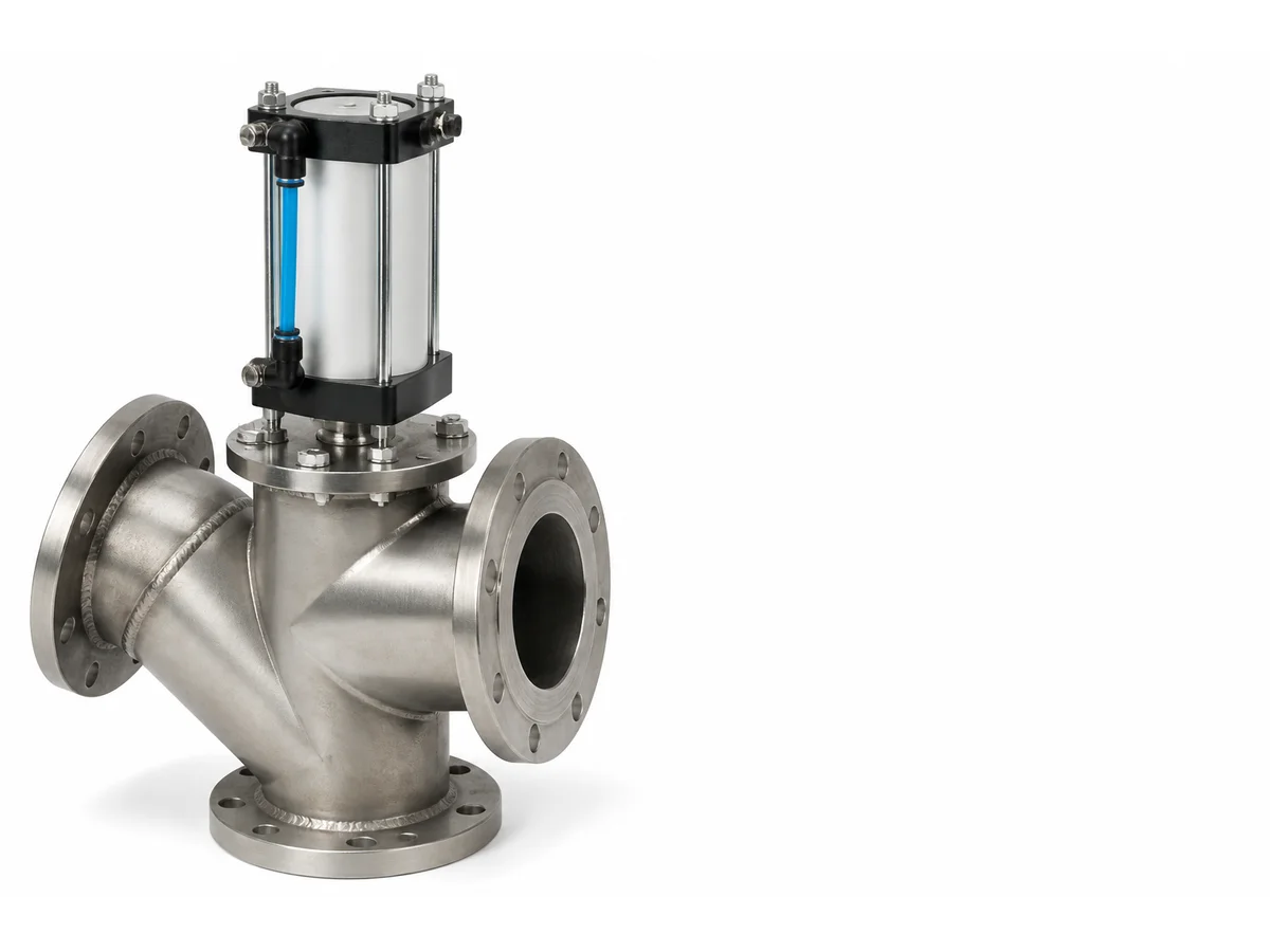
The most common installation fault on a diverter valve is letting its weight transfer into the connected tubing or piping. Line couplings are seals, not supports. Excess weight distorts the valve body, pulls the rotor out of alignment, and creates contact between moving parts — which then shows up as wear, leakage or a seized rotor. The correct approach is independent supports on the pipework on both sides plus the supplied mounting bracket, with the valve carrying nothing but its own load.
Prepare the pipe ends
Before the couplings go on, inspect the ends of the tubing or piping that will meet the valve. Remove burrs and straighten dents, and make sure the ends are square. Keep the gap between the valve and the pipe small. When the couplings are fitted, confirm the gasket does not protrude into the air stream — a gasket lip is a turbulence source, a wear point and a place for product to build up. These are small checks that take minutes at installation and hours to correct later.
Piping geometry around the valve
Alignment with the conveying system matters as much as the valve itself. Misaligned pipework loads the body and makes the diverting element work against the flow. Long straight runs into and out of the valve help the product re-establish a stable profile before and after the change of direction. Where space is tight, plan the lateral and vertical clearances for the actuator and its lever arm — and keep the rotating lever guarded.
Air supply and control wiring
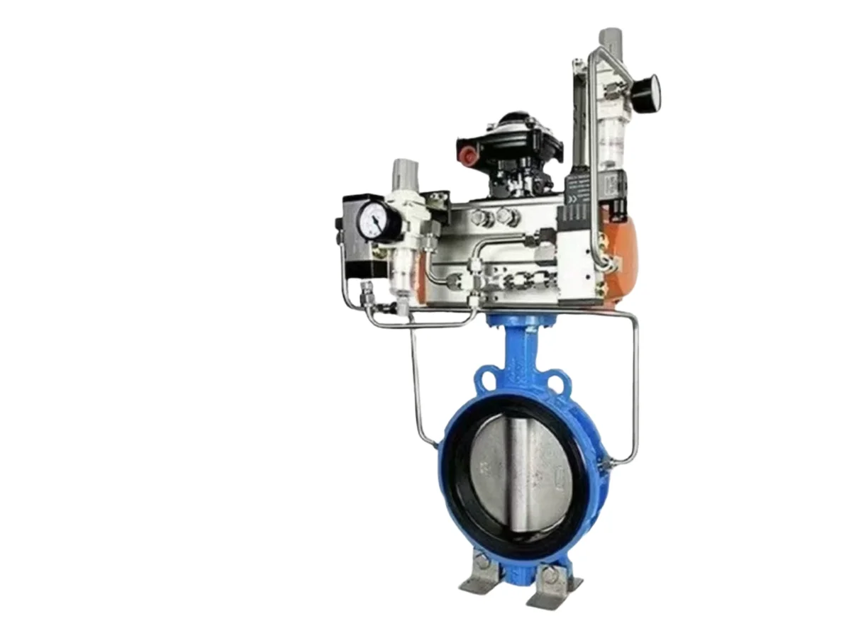
Connect the high-pressure air supply to the actuator's control valve, and use the regulator to set a stable working pressure; a supply that drifts changes switching speed and eventually causes missed positions. Wire the solenoids and position switches to the schematics, using the specified conductor size, and keep the wiring clear of moving parts. Where the valve is outdoors, protect the controls from weather. Verify the supply voltage matches the coil rating before energising — a mismatch is the most common cause of a burnt coil on a new installation.
Purging the end-plate void
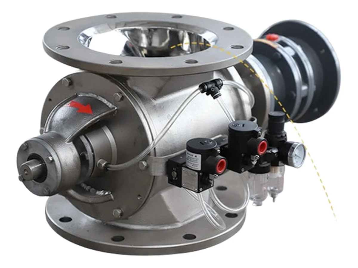
Many diverter valves provide ports in each end plate for back-pressure purging of the void between the closed-end rotor and the plate. Where the duty requires it, connect plant air to each end plate and regulate to slightly above the pressure inside the conveying line — the point is to keep product out of that void, not to blow air through the valve. The same void can be grease-packed with a food-grade lubricant instead. Either way, the purging arrangement belongs in the installation scope, not added after the line is commissioned.
Test and hand over
After installation, energise the solenoids — or switch on the motor for an electric actuator — and cycle the valve. Keep clear of the cylinder lever arm and pinch points. If unusual noise occurs, disconnect and lock out the power and check end-plate-to-rotor clearances; the rotor can shift during handling. Confirm position feedback reaches the controller on every destination. Then reinstall any guard or cover removed during fitting, and log the as-found clearances so there is a baseline for the next service.
Match the valve to the duty before it arrives
Sizing follows the conveying line, not the material; line velocity, product density, abrasiveness and pressure all refine the selection. Specify the number of outlets, the switching frequency and whether switching under flow is required, since not all designs allow it. Give the ambient temperature, the hazardous-area classification and the wash-down requirement. CHUYAO supplies diverter valves together with the pipeline, supports and control interface, so the routing point is engineered as one assembly rather than assembled from parts on site.
Wear checks and spares planning
A diverter valve wears at the seating surface where the diverting element closes off the idle leg. Once that surface erodes, product bleeds into the inactive line and contaminates whatever is stored at the far end. Hardened seats and a self-lapping sealing action slow the wear considerably, but they do not eliminate it, so the practical measure is to include the seating surface in planned inspection and to hold seals as a spare. It is also worth confirming at the specification stage that seals can be replaced without breaking the factory pipework, since that single design detail decides whether a routine seal change is a short stop or a shift-long intervention.