Double Flap Valves: The Go-To Airlock for Hot, Abrasive and Lumpy Dust
A rotary valve has clearances by design. A double flap valve has compression seals that close — which is why it takes over where a rotary airlock jams or wears out.
A rotary valve always leaks a little; a double flap valve seals by compression at each seat.
High-temperature duty is the strongest case, with designs rated well above what a rotary valve tolerates.
Large or irregular particles that jam a rotor pass through an open flap.
The trade-off is batch-wise discharge rather than a continuous stream.
Gravity flow and pressure isolation are the job; precise metering is not.
Technical Overview
What a double flap valve is
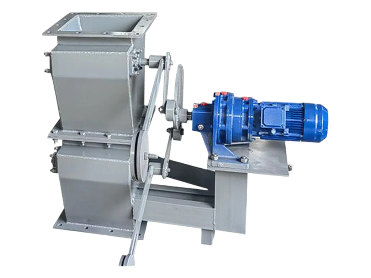
A double flap valve — also called a double dump valve or twin flap airlock — uses two flap plates separated by an intermediate chamber. They open in sequence: the upper flap opens to admit material into the chamber while the lower flap stays shut; the upper flap closes to isolate the inlet; the lower flap opens and releases the charge; then it closes before the next cycle. At least one flap is always closed, so there is never an open path between the two sides of the valve.
Why that matters for pressure separation
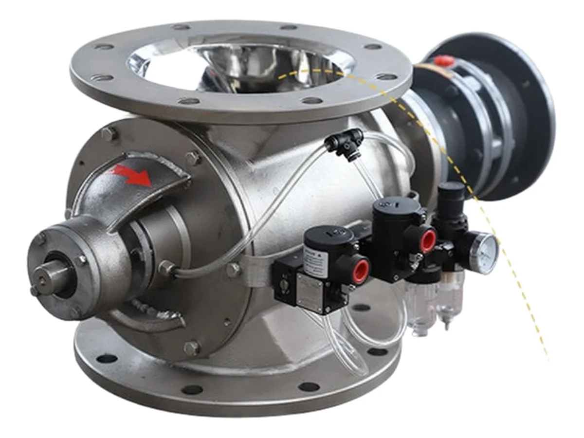
A rotary airlock meters continuously but its rotor-to-housing clearance is a permanent, if small, leak path — and it grows with wear. A flap valve seals by pressing a plate against a seat with mechanical force, giving a much lower leak rate. Where the pressure difference matters — a filter hopper discharging into atmosphere, or a vessel dropping into a pressure line — that difference decides which device belongs. It is also why the double flap is not a metering device: it discharges in discrete charges, not a controlled stream.
High temperature
Temperature is the clearest case for the flap valve. Standard designs are offered for service several hundred degrees Celsius, with special alloys extending the range further. Rotary valves at those temperatures face thermal expansion of the rotor against the housing, which is a seizure risk, and their clearances and seals have to be engineered around it. Flap valves tolerate the expansion and keep sealing. For furnace, kiln and boiler ash duty this is usually the deciding factor.
Abrasion and particle size
Abrasive products — fly ash, cement, clinker, sinter, silica — wear sealing surfaces steadily. Because the flap seats by vertical pressure rather than sliding across the seat, wear is far lower than in a device whose sealing element sweeps under load. Large or irregular particles behave differently again: they jam between a rotor tip and housing, but pass through an open flap passage. Where the product is both abrasive and coarse, the flap valve is frequently the only arrangement that runs reliably.
Drives and control
Flap valves are offered with counterweight, pneumatic or motorised drives. Counterweight operation needs no external power and suits lower duty: the flap opens under the weight of accumulated material and recloses after discharge. Pneumatic operation gives positive, repeatable cycling and integrates with a PLC sequence. Motorised drives suit sites without compressed air or where powered positioning is preferred. Whichever is chosen, position feedback confirms the flap actually reached its seat, which is what makes an interlock meaningful rather than assumed.
Getting the specification right
State the product, bulk density, particle size and shape, temperature, abrasiveness and moisture; the pressure differential and required throughput; the inlet and outlet dimensions; the drive preference; and whether the dust is combustible and the area zoned. Flap plates, liners, bearings and seals are then specified to the duty rather than to a standard build. CHUYAO supplies double flap valves integrated with the hoppers, spool pieces and discharge equipment they serve, so the sealing interfaces are drawn instead of improvised.
Sizing, actuation and integration
Double flap valves are supplied with square or rectangular inlets covering a wide range of sizes, and capacity depends on the flap area and the cycle rate rather than on a nominal bore. The valve is typically mounted beneath the hopper outlet by flange, with a spool piece to the receiving conveyor or skip. Drive options are mechanical cam, pneumatic cylinder or counterweight, and the choice follows the cycle rate and automation requirement. Because discharge is batch-wise, the receiving equipment has to accept discrete charges rather than a continuous stream — worth confirming early, since it affects the conveyor specification downstream.
Inspection and wear management
Flap plates, seats, bearings and liners can be specified against the operating conditions, and wear-resistant alloys extend service life substantially on abrasive ash. Side access doors make routine inspection of flap and seat condition quick enough to be done in practice. The maintenance routine is straightforward: check the flap seating faces for wear and deformation, check that the blade or plate moves freely, keep the pneumatic supply dry, and clear residual powder from the chamber before any extended shutdown. Where the product is combustible or toxic, the valve's containment and isolation role belongs in the documented assessment, not in a note on the drawing.