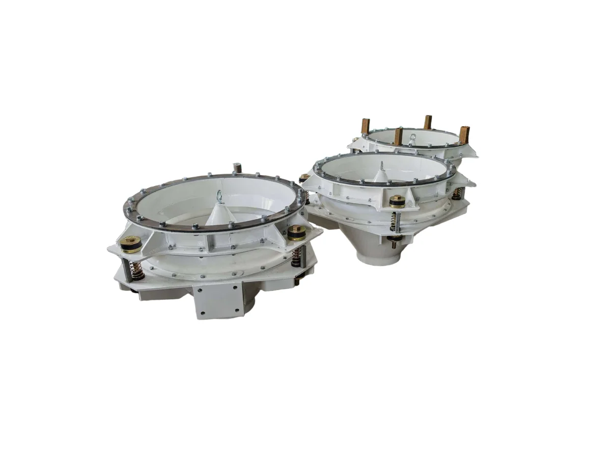
An activation hopper uses controlled vibration through a suspended cone to loosen powder above the outlet — here is the mechanism and the installation details that decide whether it works.
An activation hopper vibrates a suspended inner cone, not the silo shell, so it loosens material rather than compacting it.
Sub-resonant spring mounting amplifies the exciting force while keeping motor power low.
The discharge rate must exceed the activation rate, otherwise loosened powder re-packs at the outlet.
A flexible sleeve between hopper and silo is mandatory — rigid coupling transfers vibration into the structure and wastes energy.
Over-vibrating cohesive powder can compact it; amplitude should be tuned to the material, not maximised.
Activation hoppers suit cohesive fines that bridge or rat-hole; free-flowing granules rarely need one.
Technical Overview
Why powder stops flowing in the first place
Fine powders do not fail to discharge because they are heavy. They fail because, after a period at rest, the particles consolidate: moisture bridges, van der Waals forces and interlocking particle shapes give the bulk a measurable unconfined yield strength. The result is a stable arch across the outlet, or a vertical rat-hole that empties the centre while leaving material plastered to the walls. Conventional remedies — hammering the shell, adding a vibrator to the outside of the cone, or enlarging the outlet — often make things worse, because the energy either dissipates into the steel or compacts the powder further. An activation hopper addresses the problem differently: instead of shaking the container, it agitates the material itself across a wide zone directly above the outlet.
What an activation hopper actually is
Mechanically, an activation hopper is a short conical section installed between the silo outlet and the downstream feeder. It consists of a suspended inner cone, a polymer or rubber sealing sleeve, upper and lower flanges, a set of suspension springs, and one or two externally mounted vibration motors. The cone is not welded to the silo; it hangs from it through the flexible sleeve and spring assembly, which is what allows it to move. The interior usually carries an activation block or a curved discharge trough that extends the agitated zone upwards, so material some distance above the inlet is also loosened. Because the unit replaces the lower part of the silo cone, it also lets designers specify a shallower hopper and therefore a lower building.
The sub-resonant principle
The suspension springs are not simply supports; they are part of the drive. The system is tuned to operate just below its natural frequency, in the sub-resonant region. Working near — but not at — resonance means the spring assembly stores and releases energy each cycle, so a comparatively small motor produces a large exciting force on the cone. This is why an activation hopper typically draws far less power than an equivalent bin vibrator bolted to the shell, and why it runs quietly. It also explains a common commissioning mistake: changing the spring set or adding mass to the cone shifts the natural frequency and can drop the unit out of its efficient band, producing a machine that is noisy, hot and ineffective at the same time.
How the vibration breaks the arch
When the cone moves, it drives a horizontal, slightly gyrating motion into the powder bed. That motion can be resolved into two components acting on the bulk. The radial, or normal, component propagates outward through the bed and disrupts the inter-particle contacts and electrostatic adhesion holding the arch together. The tangential component shears the powder, so the consolidated mass yields along internal slip planes rather than holding as a solid. The practical consequence is that the effective flow channel above the outlet becomes larger than the outlet itself: instead of a narrow funnel, the whole activated cross-section moves. Material that was previously supported by wall friction and internal strength now behaves like a loosened bulk solid and flows to the feeder below.
The discharge rate rule
There is one operating condition that overrides everything else: the material must leave faster than it is being activated. If the downstream feeder, screw or rotary valve takes less than the activated volume, loosened powder accumulates at the outlet, is re-compressed by the weight above it, and a new bridge forms — often harder than the original one. In practice this means the activation hopper and the feeder have to be sized together, not independently. Where the downstream device is a volumetric screw, the designer must confirm that the screw's actual volumetric capacity at the material's aerated bulk density exceeds the activated flow; a screw that is marginal on settled powder may be badly undersized once the powder is fluidised and its bulk density drops.
Installation details that decide success
Most activation hopper complaints trace back to installation rather than to the machine. The flexible sleeve must be genuinely flexible and correctly clamped; a sleeve that is over-tightened, or a stray rigid connection such as a poorly routed dust extraction duct, will short-circuit the vibration into the silo and halve the amplitude at the cone. The silo structure must be able to accept the residual dynamic load, and the support steelwork should be checked rather than assumed. The motor's eccentric weights should be set symmetrically and locked — unequal settings on a twin-motor unit produce a swaying motion instead of a clean gyration, which fatigues the springs and cracks the flanges. Finally, the discharge chute below must be free; a blocked outlet is the fastest way to destroy the flexible sleeve.
Where an activation hopper is the right choice
Activation hoppers earn their place with cohesive, fine, consolidating powders: precipitated calcium carbonate, titanium dioxide, carbon black, milk powder, cocoa, certain pharmaceutical blends and battery cathode materials are typical candidates. They are less compelling for free-flowing granules and pellets, which usually discharge reliably from a correctly angled mass-flow hopper and gain nothing from agitation. They are also not a substitute for good hopper geometry — if the outlet is simply too small for the material's flow function, agitation will deliver an unstable, surging stream rather than a controlled one. For materials that flood when aerated, or that compact under vibration, an aeration pad or a mechanical agitator is usually the better answer, and a discharge test on the actual powder remains the only reliable way to choose.
Process Flow
Typical steps covered in this article.
Powder settles and bridges
Vibration motor excites the cone
Shear waves loosen the bulk
Enlarged flow channel forms
Controlled discharge to feeder
Typical Applications
Battery cathode and anode powder silos
Food powders such as flour, milk powder and starch