Sizing a Regenerative Blower: Read the Duty Point, Not the Catalogue Maximum
Maximum airflow and maximum vacuum are quoted at opposite ends of the same curve. Selecting on either figure alone is why blowers arrive under-sized — here is the correct method.
Every blower curve trades airflow against vacuum; the working point sits between the two extremes.
The blower sees the whole system resistance — pipe, bends, filter, receiver, not just the pickup.
Filter loading shifts the operating point, so size with the filter dirty.
Single-stage favours airflow, two-stage favours differential; neither is automatically better.
Low airflow means poor cooling; verify motor cooling at the worst-case duty point.
Technical Overview
The principle: pressure added one pass at a time
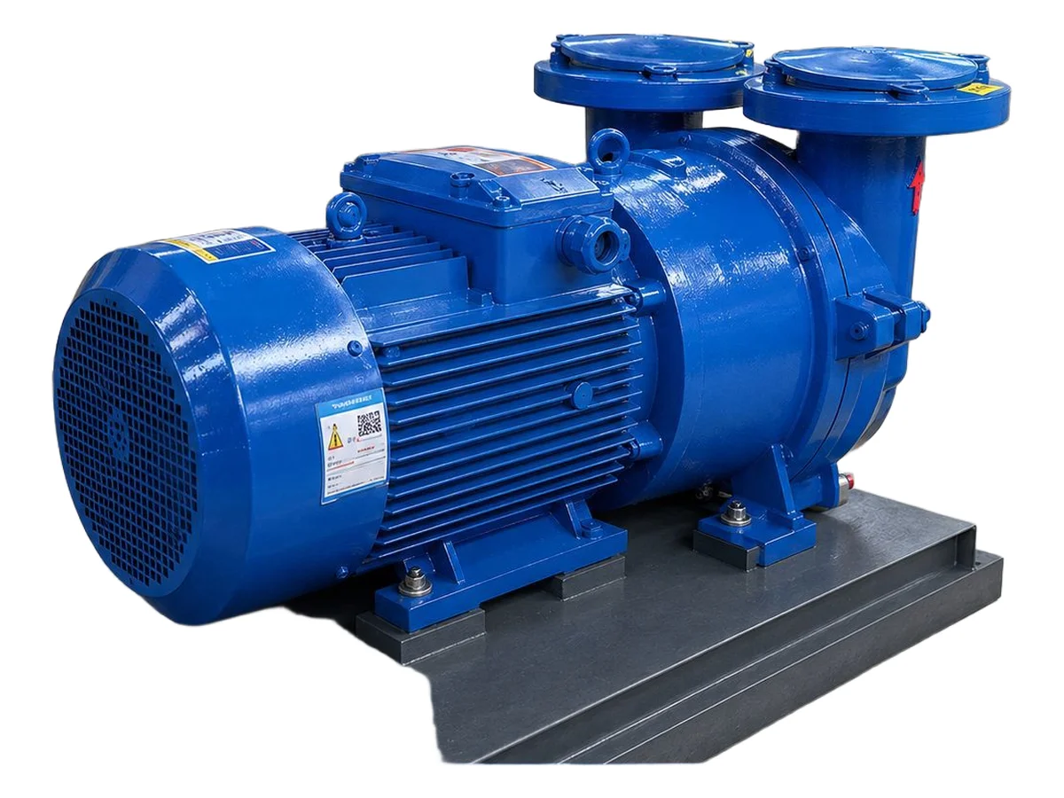
A regenerative blower — also sold as a side channel, ring, vortex or turbine blower — has a single impeller spinning in a crescent-shaped channel. Each pocket of air between two vanes is flung outward into the channel by centrifugal force, decelerates, is scooped back into the next vane pocket closer to the hub, and is accelerated again. That capture-and-return happens many times as the air travels from inlet to outlet, and every pass adds a small increment of pressure. Because the impeller never touches the housing, there is nothing to lubricate in the gas path and nothing to wear in normal service. The trade-off is characteristic: a wider impeller moves more air but regenerates fewer pressure steps, so peak differential eases.
Maximum airflow and maximum vacuum are never simultaneous
Look at any side channel blower curve and the shape tells the story. Near free air, flow is high and vacuum is near zero. At maximum vacuum, useful airflow is close to zero. Real operation is somewhere between. A specification that says only 'high vacuum' or 'high flow' is incomplete, because the duty point needs both values at the same condition: for example, so many cubic metres per hour at a stated working vacuum. A unit capable of deeper vacuum may still be wrong if it cannot supply the required flow at the working vacuum your line actually needs.
Units: gauge or absolute
Vacuum is quoted either as gauge pressure, where atmosphere is zero and vacuum is negative, or as absolute pressure, where perfect vacuum is zero. Confusing the two produces a badly wrong selection. Confirm the reference whenever you compare data between suppliers, and make sure everyone on the project — process, mechanical and controls — is reading the same convention.
Add the losses across the whole system
The blower does not see the vacuum at the pickup nozzle. It sees the sum of every restriction between the blower and the nozzle: pipe length and diameter, every bend, valves and diverters, the receiver, and above all the filter. A restrictive filter, a partially closed valve or a narrow hose can consume a large share of the available differential. This is why systems that look correctly sized on paper underperform after a few weeks: they were sized with a clean filter and then spent their life with a loaded one. Build the sizing around the dirty-filter condition and the cleaning regime becomes a control variable rather than a reaction.
Information to send with the enquiry
Ask for four things and you will get a comparable quote. First, the required airflow at the point of use, including leakage allowance. Second, the working vacuum, stated clearly in the agreed unit. Third, the route: pipe diameter, total length, number and type of bends, valves, filters and any other restriction. Fourth, the duty cycle: operating hours, ambient and process temperature, and start-stop frequency. Where multiple pickup points share one blower, say so, because diversity changes the sizing.
Single stage or two stage
Single-stage units generally give higher airflow at lower differential and suit open suction paths with expected leakage — typical of material transfer and trim extraction. Two-stage units stack impellers to reach a higher differential, which helps through long lines, denser filters or restrictive tooling. The cost is lower free-air flow, higher purchase price and greater sensitivity to running near the limit of the curve. Choosing a two-stage machine purely for its maximum vacuum figure wastes energy if the process is flow-limited, and choosing a single-stage machine for a high-resistance line leaves no margin once filters load.
Heat, noise and installation reality
As differential rises and airflow falls, less air passes through the machine to carry heat away, and discharge air temperature climbs. High vacuum operation in a warm plant room is where thermal trips originate, and repeated trips are usually a selection or installation problem rather than a fault in the machine. Noise is the other practical issue: side channel blowers have a distinctive high-frequency tone, and the published figure rarely reflects the installed sound once pipework transmits vibration or air discharges inside an enclosure. A properly sized silencer helps a great deal, provided it does not add excessive restriction. Mounting, clearance for motor cooling and protection from abrasive carry-over all belong in the installation scope — and where the product is a combustible dust, ATEX-rated motors and earthing are not optional extras.